
Table of Contents
VIOSO’s calibration kit (from 2022)
New VIOSO Calibration Kits arebased on a HiK Robotics IP camera camera. It comes with the camera body, a suitable lens, and a PoE-Injector for running the camera on any switch or directly from the PC/server.
Overview about Calibration kits based on HiK cameras:
| Calibration Kit | Description | Camera Body | Interface | Sensor size | Resolution | Lens |
| CK_W(xx) | Wideangle calibration kit | HiK CA Series | GigE | 1/1.8” | 3072 x 2048 | 89,0° x 73,8° 76,0° x 60,8° 56,8° x 44,0° |
| CK_WU(xx) | Ultra Wideangle calibration kit | HiK CA Series | GigE | 1/1.8” | 3072 x 2048 | 135,0° x 119,0° 110,0° x 94,0° |
| CK_T(xx) | Tele calibration kit | HiK CA Series | GigE | 1/1.8” | 3072 x 2048 | 44,7° x 33,9° 28,9° x 21,9° |
| CK_VF | Varifocal calibration kit | HiK CA Series | GigE | 1/1.8” | 3072 x 2048 | 97,3° x 71,5° – 28,2° x 21,2° |
| CK_FDN | Fulldome calibration kit | HiK CA Series | GigE | 1” | 2592 x 2048 | 365,00° x 185,00° |
I. Connecting the camera
Mount the camera and connect camera to PoE injector and the PoE injector to the network and power.
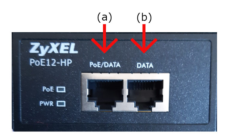
a. PoE (Power Over Ethernet)/DATA- Connect the camera to this socket (this will power the camera and a small light will flicker).
b. DATA- Connect the Ethernet cable to the PC/server or to a switch.
Important notes:
- The camera requires a stable 1Gb/s ethernet connection. 100MB/s won’t work!
- We strongly recommend running the camera directly to the PC. Therefore, VIOSO servers usually come with 2 dedicated Ethernet ports. Please note that during calibration the camera creates a large amount of data, occupying the whole network bandwidth and therefore should not be shared with other network based applications (e.g. remote access).
II. Installing the driver package “MVS” and DirectShow interface
- Download: https://vioso.com/download/hik-driver-software-mvs/
- Install driver:

- Install DirectShow Interface :
Run as Admin:
C:\Program Files (x86)\MVS\Development\ThirdPartyPlatformAdapter\DirectShow\x64\MvDSS2\InstallDSSvc_x64.bat
C:\Program Files (x86)\MVS\Development\ThirdPartyPlatformAdapter\DirectShow\x64\MvDSS\register.batFor x86 systems, run the same files from \x86 folder instead. - Reboot the system.
III. Network configuration
- Make sure that the camera is connected and powered (PowerLED “blue”)
- Run the application “MVS”.
- If the camera is connected, it shows within the “GigE” tree under the network adapter.
- If the network adapter is set to DHCP, the camera gets an address starting with “169.254…”. In this case it is required to reconfigure the network interface to a static IP. Right-Click the network adaptor and select “NIC Settings”

- In the window “NIC Configurator” click “Internet protocol properties” to access the Windows network settings. Change to static IP setting and enter an appropriate IP (e.g. 10.0.0.1 / 255.0.0.0 for a point-to-point connection). If the network already is set to a fixed IP, you can skip this step.
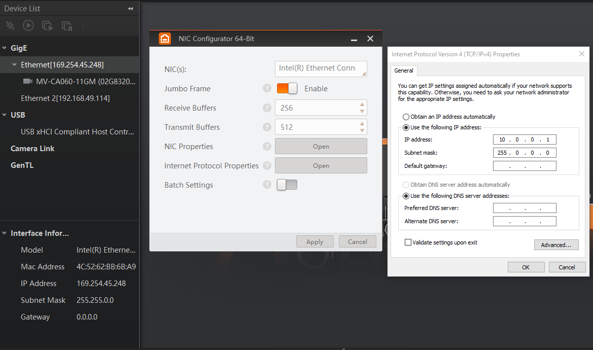
Terminate everything with “OK” and “Apply”. - Right-Click on the camera name and open the “Modify IP Address” dialog. Enter an IP that fits to the IP range entered for this ethernet connection (e.g. 10.0.0.2 according to the example above)
- This way the camera has a fixed IP, that will make all subsequent tasks for calibration more transparent.
IV. Basic configuration
All settings of the camera can be done in the “MVS” software. It is a complex tool, allowing a lot of settings to be made. But we recommend to stick to some very fundamental settings only, leaving as much as possible untreated. All settings that are done by the MVS software are persistent in the camera.
Once the camera network configuration is complete, the camera icon gets green, indicating that the camera is ready to be operated. Launch the preview by double clicking the camera and press the “Play” Button in the top button bar to display a live camera image.
Now it’s time to switch off all ambient light sources and have the projectors powered on. Use the live view to position the cameras while filming the projection surface. The projectors should display a solid color (ideally white) so that the camera can be set to an appropriate sensitivity.

Common parameters
Switch to the tab “Common Functions” to handle the most important parameters of the camera sensor:
- Acquisition Framerate: Deactivate
-
Exposure Auto: always set to OFF!
For the first time, you can set it to “once” to get an initial value of auto-exposure and start seeing a bright image, then turn it back off. - Exposure time: Set to a value that matches with the brightness of the filmed scene. By setting the exposure, the framerate automatically adapts accordingly. Please evaluate the exposure when projectors are displaying bright content, filling all the projection area.
- Gamma Enable: OFF/ON – if the camera image is too dark, enable Gamma and use either of the selectors to change to an appropriate level. Try to maintain a high contrast when setting a user defined gamma value.
Region of Interest / Image cropping
Switch to the tab “Image Properties” to crop the image. By reducing the image size, e.g. cropping unnecessary parts of the image, the frame rate can be increased, this speeding up the scanning procedure.
- Draw ROI [Edit]: Starts an interactive drawing tool that helps positioning the region of interest onto the current camera image. By dragging and resizing, the values for Offset X/Y and size of the ROI are adjusted. Click the “confirm” icon at the bottom right corner of the rectangle to activate the region of interest, thus cropping the other parts of the image
- Restore Max. ROI: resets all settings so that the whole image is used
Example: To set the ROI of a fulldome calibration kit to match the fisheye lens, set…
- Width = 2048
- Offset = 256

User settings
Even though all settings made in the MVS software are immediately stored inside the camera, it is still possible to handle multiple sets of configurations. This “User Control sets” menu is accessible from the top right button bar. Usually it is not required to handle several parameter settings, but if there is a demanding situation the usage of several user sets can help to maintain a well-controlled workflow.
You can also set “Start Settings” to be your specified User Set if you experience problems of camera losing its setting on reboots or after unplug/replugs.

V. Using the camera in VIOSO Core
Once the camera is configured, MVS software must be closed.
It is not possible to access the camera within VIOSO Core as long as the camera is opened in MVS!
The camera will show up as “DirectShow” device with a device name like “HIKRobot MV…”. All parameters are available in a large parameter tree, that can be filtered by categories and complexity (“Guru”, “Beginner”…). Though all parameters seem accessible, it is not recommended to do much changes here, because of a bad user experience:
- It is hard to browse through the vast parameter tree
- After each parameter change, the dialog closes and must be re-opened and browsed through again
For “last minute” changes, though, we recommend to concentrate on these parameters:
- Acquisition Control: Manipulate here the “Exposure time” to adjust the camera sensitivity to the test pattern displayed by the projectors
- Image Format Control: Use the values “Width/Height” as well as “OffsetX/Y” to enter a (well known) region of interest:

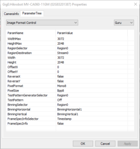
Example: To crop the image of a fulldome calibration kit to fit the lens…
- set Width = 2048
- set OffsetX = 256

Since the usability of these dialogs is challenging, we recommend to make these settings in the MVS application.
Notes about Multi-Camera usage:
- In MVS, when switching between cameras views, stop acquisition on the previous first or you will have bandwidth error warnings.
- In VIOSO MRD window (Model View Control) you might not see the camera full name in the dropdown menu. To check if it’s the right camera assigned, open the MRD file you created in a text editor. It is in XML format where
defCamNameparameter refers to the camera that calibrated the selected compound.
- Optional tip: It can be helpful to fix camera custom names in MVS (Right Click the camera > Rename User ID ). They will appear in VIOSO under “adjust camera > Options > Camera info”
VIOSO’s calibration kit (IDS/legacy)
Please note:
From Nov. 2021 some VIOSO Calibration kits use different Camera bodies. Read here how to install and operate these camera kits.
Legacy VIOSO Calibration comes with the camera body, a suitable lens, and a PoE-Injector for running the camera on any switch or directly from the PC/server.
Overview about Calibration kits based on IDS cameras:
The following instructions apply to camera kits with a body from “IDS Imaging”:
| Calibration Kit | Description | Camera Body | Interface | Sensor size | Resolution | Lens |
| CK_FDU | Fulldome Calibration Kit USB | IDS uEye CP | USB 3.1 | 2/3” | 1920 x 1200 | 360° x 185° fisheye |
| CK_FDY280 | Hyperfisheye Calibration Kit USB | IDS uEye CP | USB 3.1 | 1/2.3” | 4912 x 3684 | 360° x 280° fisheye |
| CK_WQ95/XX | Super HQ Calibration Kit | IDS uEye CP | GigE | 1.1” | 4104 x 3006 | 95,70° x 78,70° … 16,10° x 12,10° |
Connecting IDS camera
Mount the camera and connect camera to PoE injector and the PoE injector to the network and power.
a. PoE (Power Over Ethernet)/DATA- Connect the camera to this socket (this will power the camera and a small light will flicker).
b. DATA- Connect the Ethernet cable to the PC/server or to a switch.
Important notes:
- The camera requires a stable 1Gb/s ethernet connection. 100MB/s won’t work!
- We strongly recommend running the camera directly to the PC. Therefore, VIOSO servers usually come with 2 dedicated Ethernet ports. Please note that during calibration the camera creates a large amount of data, occupying the whole network bandwidth and therefore should not be shared with other network based applications (e.g. remote access).
Install IDS Software
Download and install the latest version of the IDS Software (software package) for your camera type.
After installing and rebooting, you will be able to use these programs:

IDS Camera Manager- Control the settings, camera configuration, and other functionalities.
IDS camera manager main window
If you see a yellow icon on the top of your window next to your camera, there has been an error (The error warning will be in red on the bottom of the window).

There are several warnings that can show up due to IP addresses being wrongly set, or relating to the camera’s firmware.
Configuring the camera for first use
Set a fixed IP
Before proceeding to configure the camera, make sure that the network interface is set to a fixed IP. Locate & open the IDS Camera Manager application (it can be found in: C:\ProgramData\Microsoft\Windows\Start Menu\Programs\IDS).
Learn here how to set a fixed IP in Windows:
Configure your camera
- Step 1- Run IDS Camera Manager.
- Step 2- Select the NIC that is connected to the same network as the PoE camera.
- Step 3- Select the camera from the Camera list.
- Step 4- Select Automatic ETH Configuration.
- Step 5- Close the software.
Your camera should be working correctly and the window must no longer show an error message. The main window should look like this:

Testing the camera
To test the camera, use the application “uEye Cockpit”.
 uEye Cockpit- Preview camera image and modes.

uEye cockpit main window

Display the camera stream
- Step 1- start uEye Cockpit.
- Step 2- Select Optimal colors.
- Step 3- Click on the play icon with the camera in the top-right corner (under the”File”menu).
- Step 4- Note that the image may be rotated 180 degrees if the camera is mounted “upside down”, which can be fixed by clicking on the wrench icon, selecting the Size tab, and mirroring the left/right and up/down under the “Format” section.
- Step 5- Adjust the zoom and iris settings by loosening the screw locks counter-/anti-clockwise, positioning.
- Step 6- Then appropriately using the camera feed for preview and tightening to lock them into place.
- Step 7- Close all windows when testing is complete.
Generic DirectShow
Via Direct show it is possible to use every camera, that is connected. The quality of the camera and the useabilety is in your responsibility
NDI
NDI sources can also be used for calibration. The quality of the camera and the useabilety is in your responsibility
Set up your camera
In general, all DirectShow-capable cameras are suitable for calibration if they can be set manually
For high quality, however, we strongly recommend the use of VIOSO’s own camera kits, which you can purchase from us and which are optimized for use in various scenarios (e.g. fulldome, simulation)
On our homepage you will find a camera calculator that recommends the right kit for you according to distance.
The camera used must be physically installed in such a way that it does not move during measurement and during recalibration, if possible, the entire screen should be seen in the sensor, whereby a part of the projection surface does not have to be visible, especially with round and straight surfaces.
A position that is conducive to the application should be chosen. (With 360-degree projections usually look down at the top in the middle, domes at the bottom in the middle, area mostly from the point of view of the spectators….)
All automatisms (Expo Sure, White Balance, Smearing) must be deactivated, the FOV of the camera must be known Please also note further information under wp.helpdesk.vioso.com