![]() VIOSO Anyblend VR & SIM is an extension of VIOSO Anyblend that enables you to blend multiple views created by image generators (IG’s).
VIOSO Anyblend VR & SIM is an extension of VIOSO Anyblend that enables you to blend multiple views created by image generators (IG’s).
Whether there are multiple views rendered by one client machine, one view on multiple client machines, or even a mix of both.
This software allows you to perform a full-service operation from calibrating and blending the projection to applying the calibration in different ways, as well as playback content on the calibrated projection based on a 3D work flow.
Extensions added
- Cluster calibration
- Mapping conversions- Create texture maps from a camera scan and a screen model.
- Model-based warp- Create warp and blend from model and projector intrinsic parameters without a camera.
- Calculation of viewports according to screen and eye point- Create mappings for every IG channel to the screen.
- Templated viewport export- Export a settings file that can be included to IG configuration for automatic viewport settings.
- 3D Mapping- Create sweet spot independent warp maps for head tracked CAVE™ solutions.
- Multi-camera calibration- Use fast re-calibration on screens where one camera can’t see it all at once.
- Master export- Collect all warp/blend maps on the master machine and copy them to the appropriate location on each client for VIOSO plugin enabled IG’s.
Use Cases
- Simulator setup on half dome, cylindrical panorama, or irregular screens.
- Projective Interior (virtual museum).
- Façade projections.
- Tracked CAVE™ setups.
- Projection mapping, augmented reality using textures projected on surfaces.
Main concepts of Anyblend VR&SIM
Cluster calibration
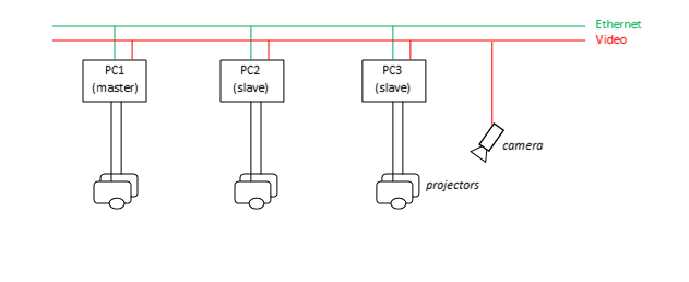
Use one or more cameras to calibrate a projection system residing in several computers. In most simulator or cave setups, there are several renderers with single or multiple outputs.
To calibrate this kind of system, we use a given Ethernet connection to calibrate a cluster. It is important that:
- Every projector is “seen” by one camera completely.
- The camera used to calibrate a connected projector must be connected to that PC. Use network camera(s) if you need a camera for multiple PCs.
 Camera to screen
Like every camera-based projector calibration, the basis of all calculations is a camera scan, which registers every projector pixel to the camera. With a few extra parameters, this scan enables us to register the screen to the camera and the projectors to the actual screen.
What benefits arise from that? Well, if you know every projector pixel’s 3D coordinate in the real world, you can calculate viewports, warp and blend maps, and eye point dependent transformations.
Projector pose to screen
This is the opposite of a camera scan. What if we already know where every projector pixel points? Of course we can take advantage of that and place a 3D model in the ray fields of the projectors and calculate warping and blending from that. So basically all features known from Anyblend can be applied to a screen or every other surface without any cameras!
Content Spaces
A content space is the image to be projected. There can be several content spaces in one setup. Content spaces are texture maps and view ports.
In a basic projection setup, the content space is the camera image plus the warping grid. Once the setup is done, all projectors are blended and there is a rectangular content image back projected through all projectors. This is the standard case for all flat-surface projections where the camera is positioned where the audience is or will be. You could also adapt the projection using our virtual canvas warp grid (VC) to adapt slightly curved screens or move the viewer’s position by adding or removing keystone characteristics.
But what if that is not enough? Content spaces enable you to transform a mapping to fit all kind of special purposes.
Projection mapping
How can I project something on a specified area on the screen? This technique is called “projection mapping” this is where an image or “texture” is warped to be projected on the screen surface. This method is similar to texturing 3D objects in virtual worlds.
For that we need a model of the screen with texture coordinates for every surface. So once we’ve matched the model with the camera and the projectors, we can read this texture coordinate from the 3D surface. Now we can sample in that image and project the image back to the real surface.

Virtual cameras
Virtual cameras are view ports to virtual-reality environments. They are defined with an eye position, view direction, rotation, and fields of view related to the virtual world.
Our projection screen can be seen as a window to a virtual world. The first step is to match the screen with the simulated environment. This is done by matching a virtual screen model on the actual screen (augmented reality approach). In other words, if we can project a virtual screen on the real screen and they match, we know which projector pixel is affected by every view port’s virtual camera image.
Then we can create a mapping, which transforms a viewport’s image to be displayed by a projector.