
This chapter describes how to perform a multi-camera calibration with a 3D-alignment approach. The workflow is based on the single camera 3D calibration, performed repeatedly for each camera, then finally merged and blended together into a single compound.
Requirements for this method are:
- Common calibration conditions
- Common multi-camera setup conditions
- 3D Model and UV map of the projection screen:
- Planes, Cylinders, Domes/Panadomes models can be generated automatically in VIOSO.
- Custom shapes can be imported in (.obj), (.dae), (.3ds) formats.
- Position and orientation measurements of the cameras relatives to the screen.
Table of Contents
Step 1: Projector scans
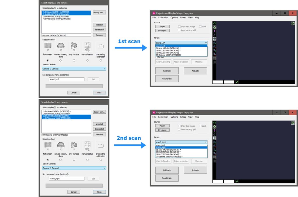
For each camera perform a calibration of the projectors that are entirely visible in its view. More details on the VIOSO projector scan can be found it here.
Don’t forget to “Set compound name” in the calibration dialogue to have your scans easily distinguishable afterwards. A good practice is to name each compound with the camera name and projectors, example: “scan_cam2_Pj4_Pj5”.
Step 2: 3D alignment
1. Create a 3D model content space
Follow this detailed guide on 3D model and content space creation.
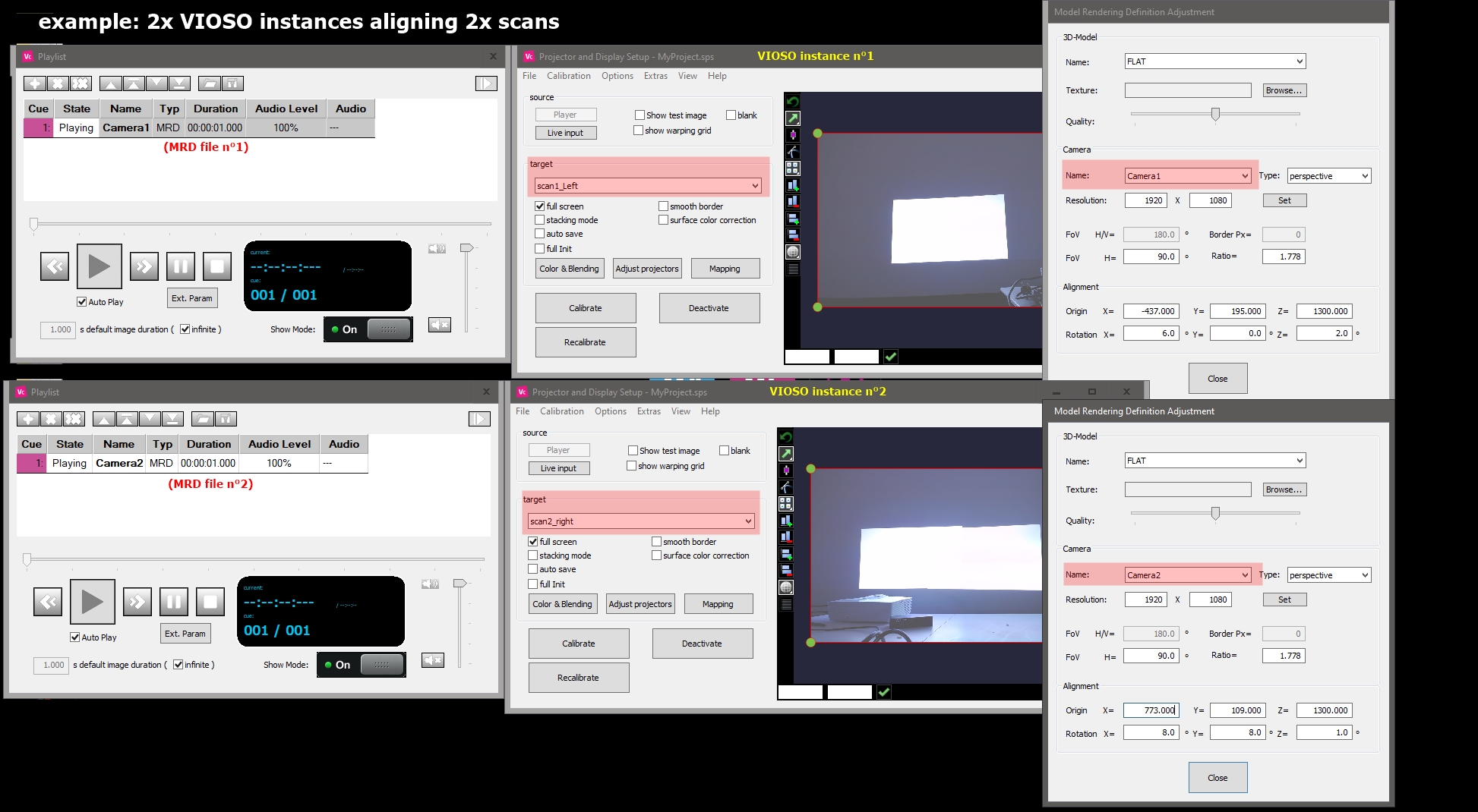
2. Align each scan in 3D space (MRD)
To have all scans visible at the same time, and be able to match them easier, you can open multiple instances of VIOSO software loading the same project, and activating a different target on each.
Note: For abstract Displays (remote-client scans) multiple instances of VIOSO must have different control ports: options > settings > multi-client > control port , switch for example to 8101 on the secondary master instance and on the client targets.
Step 3: Warping
Aligning your 3D screen in each corresponding camera view can still leave some non-matching spots in the common projection regions. This result is highly dependent on the calibration cameras and how accurate their parameters are (Intrinsics, position and orientation measurements, etc..).
This is why you can perform warping at this step to fine tune your geometry and match the different scans.
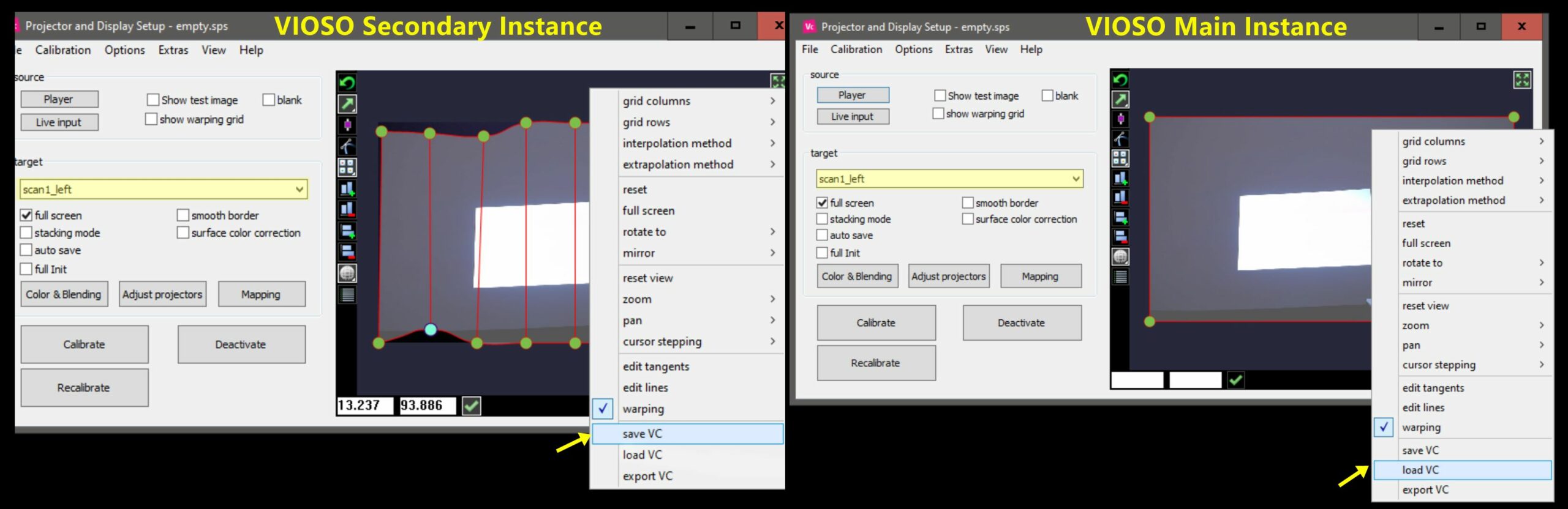
- To have all scans visible at once and match them easier, you can open multiple instances of VIOSO software loading the same project, and activating a different target on each.
- Use the warping grid to perform geometry corrections and matching.
- Save the warping by right clicking the grid then “Save VC”
- After you have done this for every scan, close the extra VIOSO instances.
- Now on the main VIOSO window, activate each scan then load the VC files you saved from the warping grid.
- Save your project.
Step 4: Conversions
1. Add VC to display geometry (Apply warping)
Once you are satisfied with the overall geometry:
-
Go to Calibration->Conversion tasks: select all the scans you warped and select the conversion format “Add VC to display geometry”.
2. Custom content space (Apply 3D alignment)
To bind the sans to their new 3D content space.
- Go to Calibration > Conversion tasks: Select your scans and choose “custom content space” then select your content space name.
Step 5: Blending Recalculation (Preceeding Calibration)
The last step is to recalculate blending of the overlapping regions between the different scans. This step is performed based only on the 3D data placed and therefore needs no camera.
- From the main VIOSO window, click on the Calibrate Button
- Select all your projectors
- Select the method “preceeding calibration“
- Set a compound name, example: “Final_All_Projectors”
- Click on Next and wait while the calculations are performed, this step can last a few minutes so please be patient.
The result now is a blended and merged single compound containing all your calibrated projectors from the different cameras.