
Table of Contents
Introduction
Using a current version of VIOSO software a 3D calibration can be done. 3D calibration uses a 3D model of the projection screen and allows to perform the alignment of the projection onto texture of the 3D model, to obtain metrically correct warping distribution across the screen surface and to include 3D data in the exported formats for integration into 3D party application, where those 3D data is required (for example for viewports calculation, frustum perspective correction for static or dynamic eyepoint).
The 3D calibration functionality is supported in the following versions of the VIOSO software:
- VIOSO ANYBLEND 5 VRSIM
- VIOSO Integrate Plus
In order to make a 3D calibration these are the main steps to follow:
- Camera calibration of the projectors
- Introducing a 3D model (Content space)
- 3D alignment (MRD)
- Final conversions
- Saving and export
Here are detailed guides for each step:
Step 1: Camera calibration of the projectors
The first step is to make a standard camera-based calibration of the projectors. If you have never done this before, you can check more details in the Core documentation together with video tutorials of the process:
It is important to not to apply any warping and VC changes at this moment! Keep the VC unwarped and fullscreen at this step, even though it is described in the tutorial as final step – for 3D calibration the VC should be left fullscreen.
We also recommend to use full resolution of the camera for calibration, because later you will need to insert the FOV of the calibration camera used. The Field of View for the camera can be usually found in datasheet and it is given for the full resolution usage, so if you have used cropped camera image for the calibration you will need to recalculate the camera FOV by yourself.
Step 2: Introducing a 3D model (Content space)
When you perform the calibration using a camera, the calibration result will be mapped using the calibration camera perspective, so camera – is the default content space for the calibrated projection.
However, by the most of applications the content must be displayed and evenly distributed onto a projection surface or onto your custom content space. The custom content space for the calibration in this case is the surface of the 3D model which is used for projection which has to have a UV texture coordinates distributed properly on the projection surface.
If you have a regular shape of the projection screen we recommend you to use our built in tool for 3D model creation. It will generate a 3D model automatically based on the inserted parameters, provide with proper texture coordinates distribution and assign it to the content space.
Here you can find the detailed guide on how to use VIOSO software to create a 3D model and content space:
You can also use your own custom 3D model and import it into VIOSO software. Example: creating a simple model in SketchUp.
Currently following formats are supported:
- *.obj
- *.dae (COLLADA)
Step 3: 3D Alignment (MRD Adjustment)
Once the camera calibration is made, and a 3D model is introduced to a system as content space, the 3D alignment can be done. Here is a detailed guide of this process.
We recommend to align the camera position in 3D alignment as good as it possible before making a final touches using the warping grid.
Step 4: Final conversions
Before performing the conversion it is recommended to save the progress into a separate calibration file. The conversions are mathematical recalculations which cant be reverted, thus if you would require to go back – you will need the calibration file saved before this step.
So, there are two conversions to be made to achieve the final result:
- Add VC to display geometry
- Custom content space conversion
1. Add VC to display geometry conversion
If any warping has been done during Step 3 (3D adjustment), you have to fix those warpings into 3D data of the diaply compound your are working on. The first conversion will perform this operation, and add your VC to the display geometry.
To perform this conversion go to menu “Calibration->Conversion Tasks”
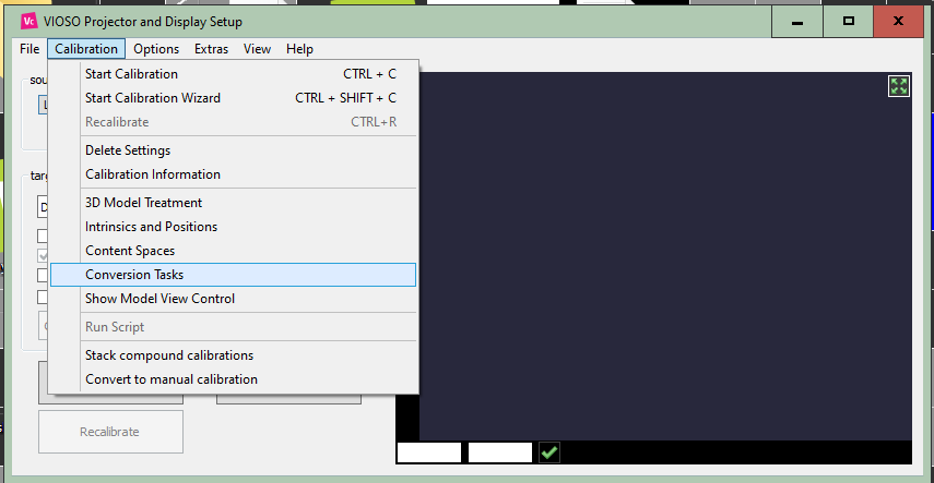
Select the compound you are working on, select the conversion “Add VC to display geometry” and click perform:
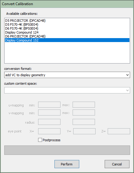
Now you have fixed your warping VC into display geometry.
2. Custom content space conversion
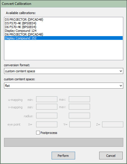
Next step is to convert your calibration from default camera content space into the content space of your 3D model (your custom content space). To perform this conversion go to menu “Calibration->Conversion Tasks”:
Select the compound you are working on, select the conversion format “custom content space”. Then select your content space (your 3D model) that has been created in Step 2 of this guide, and click perform.
The 3D calibration is finished at this point, if you “activate” your compound in VIOSO and tick “show test image” it should display the pattern in the desired texture distribution that you aligned previously.
Make sure you save the converted calibration with a different name so that you don’t overwrite the progress achieved up to this step, as conversions cannot be undone.
The result is ready for usage in Anyblend or for export to any third-party applications that require 3D data (example: vwf for Unity, MPCDI v2 for Unreal..etc).
Optional: Recalculate Blending
In addition, you can use the 3D data acquired to recalculate blending. In many cases, it can improve its precision and quality.