
Once a calibration is done, you can align it using 3D model data and virtual camera positioning.
In order to perform 3D alignment, you will need:
- The initial calibration (completed) with blending. No VC adjustment and no warping.
- The 3D model of the screen with its UV map (refer to the previous step for details: 3D model creation).
Steps
- Load the calibration in VIOSO and activate it, so you can see the calibration result on the projectors.
- Make sure the warping Virtual Canvas (VC) is untouched and it is set by default to full screen.
- Open the player view. On the main menu, click the plus icon. Then choose ‘Add Model Item’ then ‘Add MRD’ – give it a name — this will create an MRD file in the playlist.
- Double-click on it to activate it, so it is in “playing” status.

- On the main window, un-check the “Show test image” checkbox, as this test pattern will always be shown on top of playlist content.
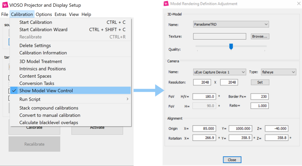
- Click the “Calibration” menu on the main Core window and choose ‘Show model view control’.
-
 Align the virtual camera parameters to your real calibration camera measurements. Refer the sections below for details and examples.
- The 3D alignment is now finished, you can proceed by performing the conversions
Model Rendering Definition window parameters:
3D model
| Name | Select your 3D model from the list of created custom content spaces |
| Texture | If there is a custom texture that you would like to apply to your model, click ‘Select’ to browse an image from the disk. The default models created by VIOSO will have the texture file automatically created and filled in this field. |
| Quality | slider to increase/decrease the preview quality of the rendered texture |
Camera
| Name | Name of the camera. from V5.3+ it is automatically selected |
| Type | Type of the lens (Perspective or Fisheye) |
| Resolution | Resolution used by the camera during the calibration, if you did any cropping or ROI define here the final pixel space used. From V5.3+ it is automatically detected |
| FOV | Refer to the lens specifications, Values are usually for perspective (50-110) & fisheye (180-185) |
| Border px | If the camera has a lens that crops some areas of the sensor – fill out the dimension of the border of cropped pixels. It’s most frequently used with fish eye lenses – around 250px |
| Ratio | Resolution X/Y , usually automatically calculated |
Alignment
This is the most important setting where you put the measured pose of the camera from the origin of the screen.
| Origin: | Translation values: (Y up, X right, Z backward) |
| Rotation | Rotation values (X pitch, Y yaw, Z roll) |
The translation and rotation are defined in the system coordinates of the 3D model on screen, where the camera pose is originally as shown below:


If you created the 3D model from the VIOSO software, it will be in the right hand system, and the (0,0,0) origin is located:
- Flat plane: Bottom center line.
- Cylinder: At the center of bottom circumference.
- Panadome/Dome: At the center of the sphere.
Example: Top-down fisheye camera on a panadome screen:
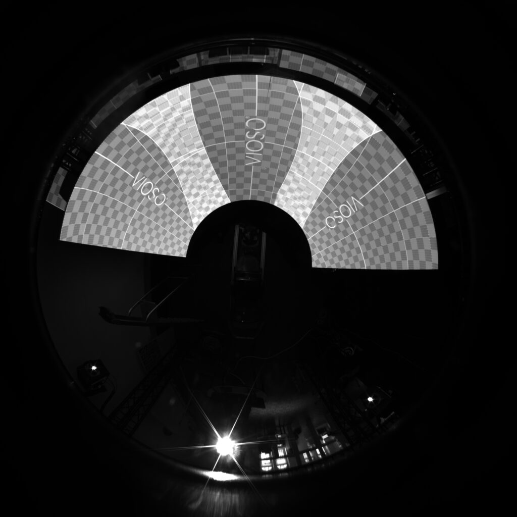
The camera is mounted on top of the screen pointing down, it is rotated 90 degrees counterclockwise around axis X, meaning rotation x will be -90 or 270.
Our screen is a panadome and the camera is mounted on top of the screen in the center,meaning that it is located at some height relative to center of the sphere (origin) -> Y translation.
By adding these parameters you will start to see grey texture on the projection screen. This is the real-time rendered image onto the UV texture of the 3D model you have introduced to the system.
To find the best values to position your texture and align it onto your real screen, use all the camera position parameters and border px parameter.
- You can type the values in fields from the keyboard. You can use the scroll-wheel or you can use the keyboard arrows.
- If you hold SHIFT and change the value in the field, it will change with bigger steps (coarse).
- If you hold CTRL and change the value in the field it will change with smaller steps (fine).
Align the testing grid as good you can by carefully tweaking all of the values mentioned above. It is natural that this procedure takes a time.
It is recommended to position the grey test picture in a way that it overshoots the screen a little bit, so that you get rid of the aliased edge of the texture and later mask it out.
If you did your best and the alignment is still not perfect, you can use the warping tools in the VC grid of the main window (Refer to the VIOSO Core Warping section to know more)
Note that warping will be still in camera perspective, as the calibration is not converted yet.
When you are done, click on “close”, the pose will be saved automatically.
Now you have completed the 3D MRD alignment of your calibration. The final step is to perform the conversions