
Camera intrinsic parameters
“Intrinsic parameters” describe the internal parameters of a camera. These values never change during the lifetime of a camera. They depend on the aperture and the lens. There is a set of intrinsics for every resolution, zoom level, focus, and iris (shutter) setting. So these parameters must be constant on a setup.
Thus every camera must be tested on the setup to capture the right scene by adjusting focus and iris and then calibrated using the exact same settings.
Camera calibration enables us to know which ray is captured by which camera pixel. The parameters are:
- Resolution width and height in pixels.
- Focal length in width and height in pixels.
- Principal point (image center) in pixels.
- Radial and tangential distortion .
Intrinsic parameters are calculated from a set of test patterns presented to the camera.
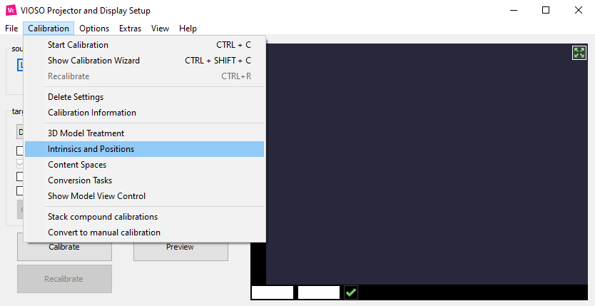
Just print out the provided pattern, save the captured images, and calculate the intrinsic parameters. To do this, go to the “Calibration” menu on the core main window and choose “Intrinsic and Positions”.
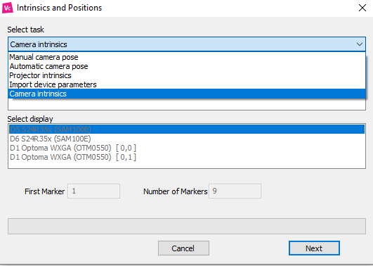
On the Intrinsics and Position window, drop the menu on “Select task” and choose “Camera intrinsics”.
To do this, perform the following steps:
Step 1- Setup the camera and find the best settings for resolution, focus, zoom, and iris.
These values must never be changed again or you have to re-calibrate the camera!
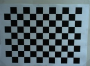
Step 2- Print out the chessboard patterns provided in “%installpath%\TestPatterns”. DO NOT RESIZE! DOUBLE CHECK PRINTED SQUARE SIZE! The process depends on real sizes, so all checkers have to be square shaped with known size in millimeters (mm). It is recommended to fix them on a sturdy cardboard because they have to remain perfectly flat throughout the process.
Step 3- Open your favorite camera capture utility. You can use IDS Cockpit or VLC.
Step 4- Create a directory with the same name as your camera.
Example: “D:\Logitech Webcam C930e” or “D:\uEye capture device 1”
Step 5- Create directories named for every test pattern: COLUMNSxROWS_SIZE
Example: For the provided test image “pattern_A3_12x9_30.png”, which has 12 by 9 checkers sized 30mm, create a directory named: “12x9_30”
Step 6- Save a set of 9 pictures for every pattern this way (use png or 24-bit bitmap format):
Central, filling
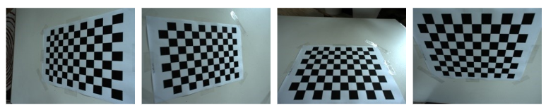 4x edge tilt
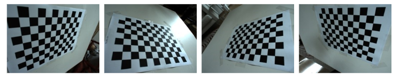 4x corner
Step 7- Use at least two pattern types!
Step 8- Go to the “Calibration” menu on the core main window. Choose “Intrinsic and Positions”.
On the Intrinsics and Position window, drop the menu on “Select task” and choose “Camera intrinsics” and press ‘Next’. Browse for the directory named after your camera.
Step 9- After about 10 seconds (1/2 sec per image), you’ll get a display of the intrinsic parameters. Check the back projection error–it should be less than 1 for a high-quality camera.
Step 10- You can inspect the calibration results in the data exchange TEMP directory. There are log files as well as back projection test images.
Once the intrinsic parameters are calculated, we can triangulate the camera’s position from known 3D coordinates in the real world. To do this, go to the “Calibration” menu, choose “Intrinsics and positions”, and then “Camera position”.
Calculate a camera position and orientation
By calculating a camera position, you register the view rays of each camera pixel to the real world, respectively, for your designated screen.
To do this you need:
- At least 6 “real” points physically marked on or around your projection surface (the projection surface you have 3D coordinates from). They should correspond to the model used, if any.
- Make those points visible to your camera. Use big and contrasting markers, or augment features by using a laser pointer/cross hair.
- Calculated intrinsic parameters for that camera.
Put markers on or around the screen. Measuring real coordinates works best, and be as accurate as possible! If you calculate 3D points on a cylinder/dome, measure the cords to obtain the angles. A protractor often is not accurate enough, as you’ll need +/-1 arc minutes, which is +/-0.0166 degree. That is about +/-1mm at 3 meters radius.
Edit the “SPMarkerDef.ini” found in your data directory. Enumerate from 1, continuous, you can define several sets by choosing start and counting the markers. You can have a 3D coordinate multiple times. Here is what a definition file looks like:
<?xml version="1.0"?>
<VIOSO>
  <File version="1.0.0" />
  <Marker id="1" X="-200.0" Y="-200.0" Z="0.0" />
  <Marker id="2" X="-200.0" Y=" 200.0" Z="0.0" />
  <Marker id="3" X=" 200.0" Y=" 200.0" Z="0.0" />
  <Marker id="4" X=" 200.0" Y="-200.0" Z="0.0" />
  <Marker id="5" X=" 0.0" Y=" 0.0" Z="0.0" />
  <Marker id="6" X="-400.0" Y=" 300.0" Z="0.0" />
  <Marker id="7" X="-400.0" Y="-300.0" Z="0.0" />
  <Marker id="8" X=" 400.0" Y=" 300.0" Z="0.0" />
  <Marker id="9" X=" 400.0" Y="-300.0" Z="0.0" />
</VIOSO>
Go to Calibration->Intrinsics and Poses->Manual camera pose. Select the camera and a control monitor. Enter first the number of markers. Click Next. Select the camera mode you have calculated intrinsic parameters for. Click Next.
Move the markers using the mouse (left moves the marker, wheel zooms, right pans) and arrow keys. You always move the point next to the mouse cursor, indicated by a circle drawn around the cross.
Once all points match the markers, get your UI in front (use F2 or right click), select the camera intrinsic, and press Calculate. Double check the pose, save an image (saved in data directory), and press Finish.
Calculate a camera position and orientation
Projectors have intrinsic parameters as well. We need them if we want to use a projector’s ray field to do advanced projection mapping like using several trackable objects to project on.
To calculate them, you need a flat screen. Register your camera to the screen to have 3D coordinates for every camera pixel. (see Register a projector to the screen)
In Calibration->Intrinsics and poses/Projector intrinsics. Select your projector and camera (you need intrinsic parameters!) and click Next.
Now use a tripod and project images from different angles similar to a camera intrinsic measurement. Finish by pressing Calculate and Finish.